< Previous | Contents | Next >
The OUTPUTS tab displays all the output devices including output, PGM, activation ports and Z-Wave. The AUTOMATION tab displays all the panel’s Z-Wave and PowerG+ automation devices.
In this tab the devices can be:
• Viewed
• Controlled - Turned on or off. You can enable PowerMaster devices to turn on for specified time periods.
• Configured – set icon and label
You can only control the devices for defined time periods after an alarm event. To define this time period:
1. Click Settings.
2. Click RESOLVE.
3. Click Automation Activation settings.
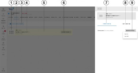
Figure 21. Output tab
Callout | Name | Description |
1 | Output Icon | Describes the output functionality. It can be set in CONFIGURATION (callout 8) |
2 | Output number | Unique output number. In DSC panels 1001 means first output (121) partition 1. |
3 | Control status | Most of the time it says in red ‘Output can be only activated during 5 minutes since alarm received’. After an alarm there is a blue comment saying outputs can be activated. |
4 | Output label | Output label which can be set in CONFIGURATION. |
5 | Output row | Each PowerManage output device gets one row. |
6 | SUBMIT STATUS | After alarm event the pull down button can control the output state. |
7 | DEVICE CONTROL | When selecting an output row a dialog appears with DEVICE CONTROL tab with the ability to turn on/off the output device after an alarm. |
8 | CONFIGURATION | When selecting an output row a dialog appears with CONFIGURATION tab with the ability to define icon and label. |
9 | SUBMIT STATUS | In DEVICE CONTROL tab after an alarm event the pull down button can control the output state. |