Devices tab
Navigating the Devices tab
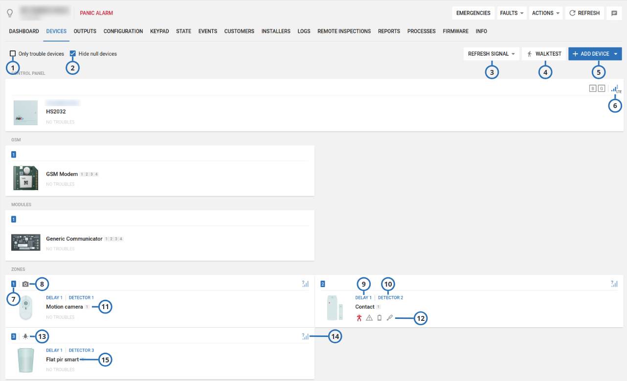
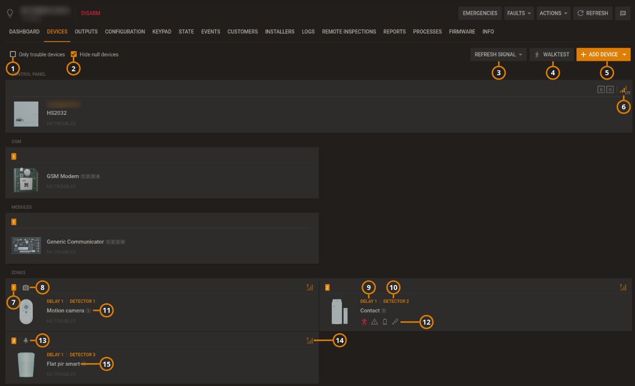
Manage all devices that connect to a panel on the DEVICES tab.
Figure. Navigating the DEVICES tab
| Callout | Name | Description |
|---|---|---|
| 1 | Troubles check box | To only display devices with troubles, select the Only trouble devices check box. |
| 2 | Hide null devices | To hide devices with no functionality, check box. note This icon is only displayed after receiving a temperature or light data report. |
| 3 | REFRESH SIGNAL | |
| REFRESH GSM: Click to see GSM/cellular signal strength of panels. | ||
REFRESH RSSI: To refresh the Received Signal Strength Indication (RSSI) for the panel and its connected devices, click REFRESH RSSI. note There are two types of radio frequencies: GPRS connects the panel to the server with a cellular modem and PowerG connects wireless devices to the panel. | ||
| 4 | WALKTEST | Click to perform a walk test on all eligible devices. A walk test discovers if wireless stationary devices are operational and reporting event information to the panel. For more information, see Performing a walktest on all eligible devices. |
| 5 | ADD DEVICE | Click to pre-enroll a new wireless device on the panel with the device enrollment ID and zone number. |
| 6 | Panel RSSI | Displays the Received Signal Strength Indication of the panel's cellular connection. note The ? icon indicates that no RSSI measurement exists, see callout 9. |
| 7 | Device number | The device number refers to the zone number for a sensor and the index number for infrastructural devices, such as a keypad, siren, or repeater. |
| 8 | Camera | The camera icon indicates that the device has video capabilities and you can view the device's video footage in the examination pane. |
| 9 | Device zone type | Displays the device's zone type. Examples of zone types are perimeter, home delay, interior follow, or fire. |
| 10 | Location | Displays the location of the device. note For PowerMaster panels, the location of zoned devices displays. For Neo/PSP panels, the label of the device displays. |
| 11 | Partition | Displays the partition that the device is in. |
| 12 | Trouble icons | Displays all of the troubles that affect the device. Hover over an icon to see a description of the trouble. |
| 13 | Smart sensing | The smart sensing icon indicates that the device has smart temperature and light sensing features. If the device has the smart sensing icon, you can view temperature and light readings on the METEO tab. For more information, see Temperature and light readings on the METEO tab. |
| 14 | RSSI level | Displays the Received Signal Strenth Indication (RSSI) of the RF PowerG connection. note The ? icon indicates that no RSSI measurement exists. To refresh this level, press the REFRESH RSSI button. |
| 13 | Device type | Displays the device type. Examples of device types are contact, LCD keypad, and motion outdoor camera. |
Figure.
| Callout | Name | Description |
|---|---|---|
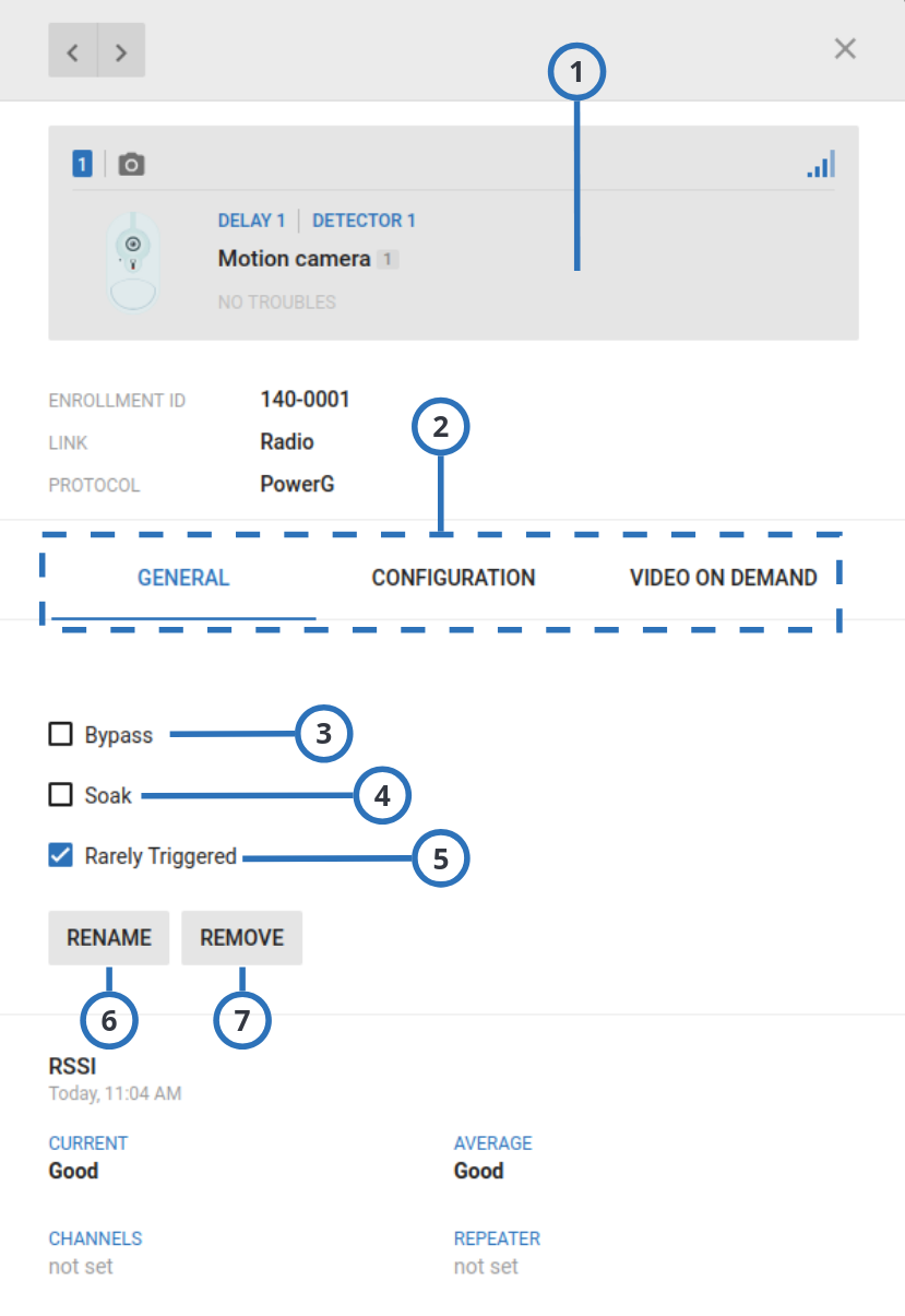
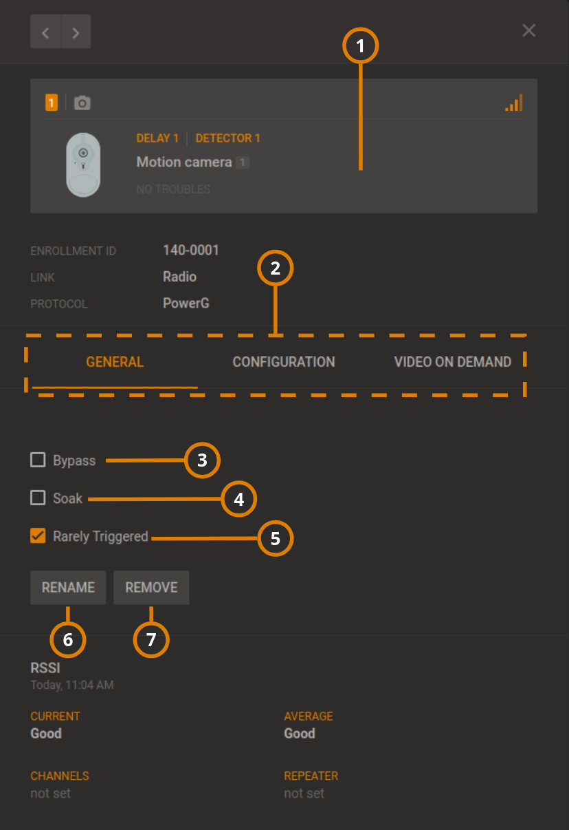
| 1 | Examination pane | The examination pane appears when you select a device on the DEVICES tab. |
| 2 | Examination pane tabs | Depending on a device's features, the examination pane displays interactive tabs for the device. |
GENERAL: View general information about the device and perform general tasks on the GENERAL tab. On the GENERAL tab, you can view or refresh RSSI information, rename or remove a device, bypass or soak a device, and mark a device as rarely triggered. For the IQ panels, the GENERAL tab displays the following commands.
| ||
| CONFIGURATION: On the CONFIGURATION tab, you can view and edit device configuration settings, such as the location, RFID number, enrollment method, zone type, chime and subtype. To ensure the information is up-to-date, click REFRESH. If no configuration is available, click DOWNLOAD NOW. | ||
| VIDEO ON DEMAND: Appears if the device has video capturing capabilities. To view the video footage of video on demand device, click the VIDEO ON DEMAND tab. For more information, see Using the video on demand tab. | ||
| PARENT: Appears if an auxiliary device is wired to a parent device. To view the parent device, click the PARENT tab. For more information, see Using the PARENT and CHILDREN tabs. | ||
| CHILDREN: Appears if a parent device connects to an auxiliary wired device. To view the child device or devices, click the CHILDREN tab. For more information, see Using the PARENT and CHILDREN tabs. | ||
| METEO: Appears if a device has smart sensing features. To view the temperature and light data of a smart detector, click the METEO tab. To find the smart sensing icon, see Smart sensing. For more information on the METEO tab, see Temperature and light readings on the METEO tab. | ||
| FIRMWARE: Displays the relevant firmware upgrades that are available. | ||
| CONNECTION STATUS: Displays the status of the IP and cellular communication channels. | ||
DIAGNOSTIC: Displays the power statistics of the panel. To refresh this information, open the panel in the Equipment hub, click ACTIONS, then click Read Diagnostic. For more information, see ACTIONS in Navigating the equipment hub. note The DIAGNOSTIC tab feature is available for Neo and PSP panels only. | ||
TEMPERATURE/LIGHT STATISTIC: View all the previous temperature and light measurements of a device. This feature is only available for smart devices that can sense temperature and light. To enable temperature and light recording, see Group parameters. | ||
| 3 | Bypass | To disable a device from triggering an alarm, select the Bypass check box. The device is not bypassed after the next arm or disarm state change. |
| 4 | Soak | To put a device in a soak state in order to monitor for false alarms, select the Soak check box. A device that is in a soak state does not create an alarm but a soak event. |
| 5 | Rarely triggered | Device inactivity causes a remote inspection test to fail. If a device is not expected to trigger often, select the Rarely Triggered check box. note For more information on remote inspections, see Remote inspections tab. |
| 6 | RENAME | Click to rename a device. note For PowerMaster panels the name saves on the server. For Neo and PSP panels the name saves as a label in the panel. |
| 7 | REMOVE | Click to remove a device from the panel. |
- Equipment hub
- Adding a wireless device to a panel
- Bypassing, soak testing, and marking a device as rarely triggered
- Editing the configuration of a device
- Performing a walk test on all eligible devices
- Refreshing the Received Signal Strength Indicator of a panel
- Renaming or removing a device
- Temperature and light readings on the METEO tab
- Using the VIDEO ON DEMAND tab
- Viewing device video footage
- Viewing all devices with troubles in a panel
- Viewing device smart temperature or light readings
- Using the PARENT and CHILDREN tabs
Adding a wireless device to a panel
- Click the panel name in the PANEL column on the Equipment page to open a panel in the Equipment hub.
- Click ADD DEVICE.
- Enter the enrollment identification number in the Enrollment ID field.
The device ID is on the device's label, written in the following format: ID: XXX-XXXX. The first three digits of the identification number indicate the device type and the remaining four digits are unique to the device.
- Enter the desired zone number or the device number.
- Click ADD.
The device is now pre-enrolled. To complete the enrollment process, refer to the device manual.
Refreshing the Received Signal Strength Indicator of a panel
- Click the panel name in the PANEL column on the Equipment page to open a panel in the Equipment hub.
- Click REFRESH RSSI.
Viewing all devices with troubles in a panel
- Click the panel name in the PANEL column on the Equipment page to open a panel in the Equipment hub.
- Select the Show devices with troubles check box.
Performing a walk test on all eligible devices
- Click the panel name in the PANEL column on the Equipment page to open a panel in the Equipment hub.
- Click the DEVICES tab, and then click WALKTEST to view the devices that are eligible for a walk test.
- Click START WALKTEST.
Figure
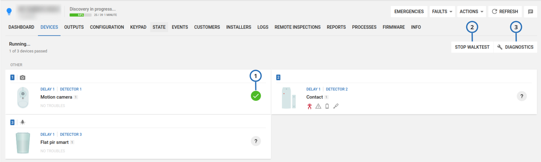
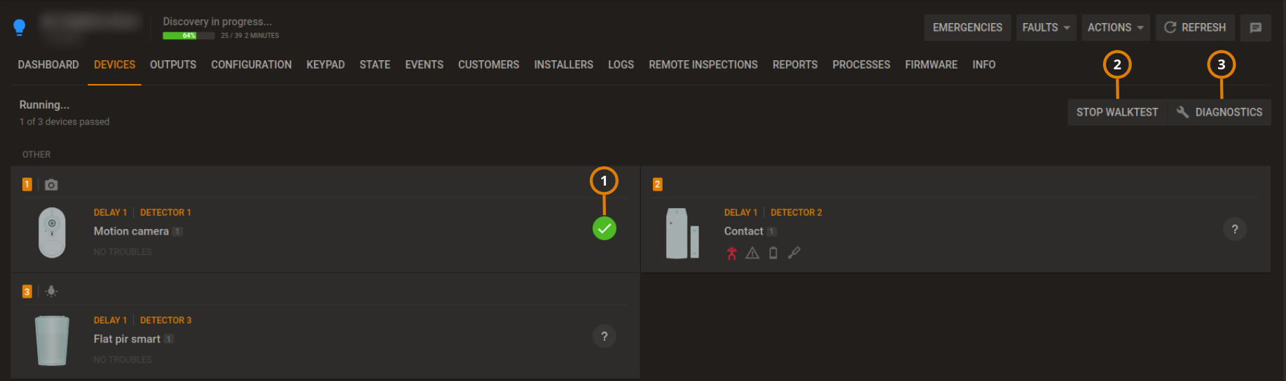
| Callout | Name | Description | |
|---|---|---|---|
| 1 | Walk test result | Waiting for walk test: the device has not yet passed the walk test. | |
| Walk test failed: you have not triggered the device before the walk test ends, or the panel has not detected the event. | |||
| Walk test successful: you triggered the device, and the panel detected the event. | |||
| 2 | STOP WALKTEST | Click to stop the walk test: the button label changes to START WALKTEST. | |
| 3 | DIAGNOSTIC | Click to return to the device display. | |
- Neo panel walk test ends if you click STOP WALKTEST or the test times out.
- PowerMaster panel walk test ends if all sensors are activated or the test times out.
Bypassing, soak testing, and marking a device as rarely triggered
- Click the panel name in the PANEL column on the Equipment page to open a panel in the Equipment hub.
- Select the device to bypass, soak test, or mark as rarely triggered in the DEVICES tab.
- On the GENERAL tab in the examination pane, select one of the following check boxes to perform the action:
- Bypass
- Soak
- Rarely Triggered
Renaming or removing a device
- Click the panel name in the PANEL column on the Equipment page to open a panel in the Equipment hub.
- Click the device to rename or remove on the DEVICES tab.
- From the GENERAL tab in the examination pane, select one of the following options:
- Click RENAME and enter a new device name in the Name field.
- Click REMOVE.
- To confirm, click RENAME or REMOVE.
Editing the configuration of a device
- To open a panel in the Equipment hub, on the Equipment page, click the panel name in the PANEL column.
- On the DEVICES tab, select a device to configure.
- To view the device configuration settings in the examination pane, click the CONFIGURATION tab. To ensure the con- figuration is up-to-date, click REFRESH. If there is no configuration information, click DOWNLOAD NOW to download the most recent configuration data from the device.
- Edit the required settings. To undo a change, click the undo arrow to the left of the field.
- To upload the configuration changes to the panel, click UPLOAD. UPLOAD appears above the configuration when you edit at least one field.
Using the VIDEO ON DEMAND tab
The following panel setups have video on demand capabilities:
- All PowerMaster panels
- PSP&NEO panels with software
1.0,1.1, and1.2that have a FIBRO connection - PSP panels with software version
1.3and later that have an ITv2/FIBRO connection - IQ panels
4.6.0iand above support for video on demand (VOD), video verification (VV), and peek-in videos, using the LwM2M protocol
It is recommended to use the LwM2M protocol for IQ panel connection with PowerManage. Use the Fibro connection if you want to use PowerManage as panel event’s receiver only.
To view device video on demand in the VIDEO ON DEMAND tab, on the DEVICES tab, select a device with the camera icon. For more information, see camera in Navigating the Devices tab.
- For more information on changing the video on demand settings for all devices with video, see CONFIGURATION tab.
- For more information on changing the video on demand settings for an individual device with video, see the CONFIGURATION tab of the device on the DEVICES tab.
Video on demand
Figure. Navigating the VIDEO ON DEMAND tab
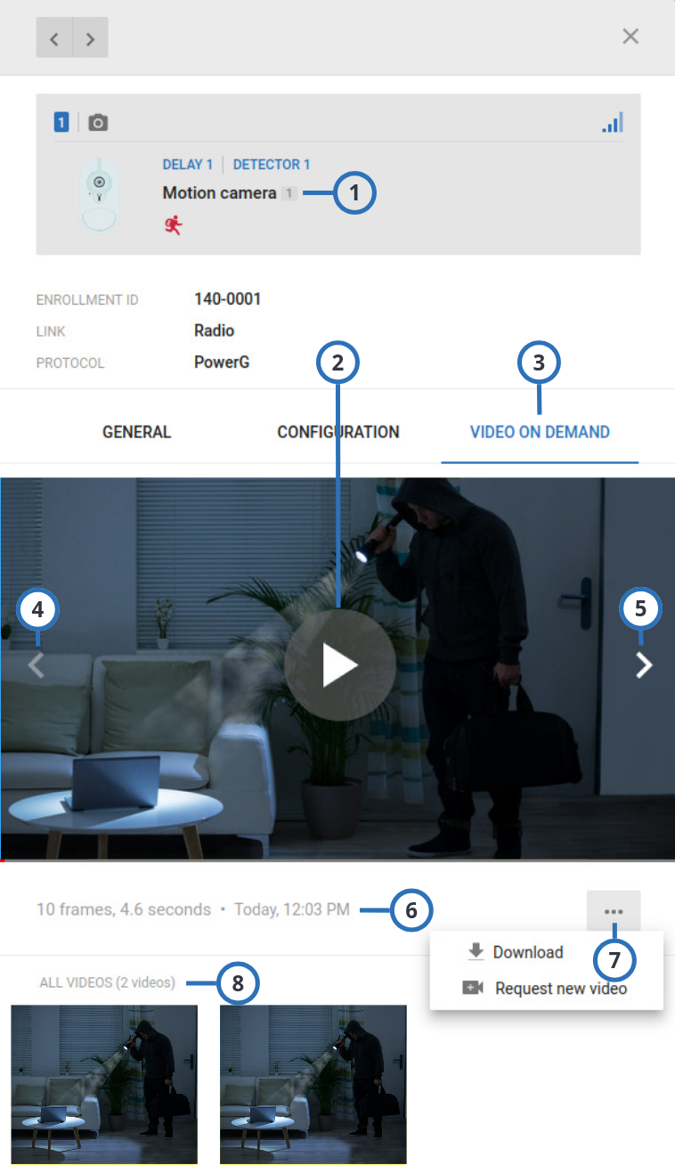
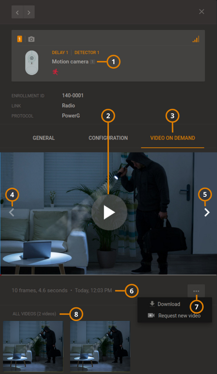
| Callout | Name | Description |
|---|---|---|
| 1 | Device type | Displays the name of the device, remaining battery life, and **** |
| 2 | Play button | Click to play the video and enlarge the screen. |
| 3 | VIDEO ON DEMAND | Click to open the VIDEO ON DEMAND tab. |
| 4 | Back skip arrow | Click to skip backwards one frame. |
| 5 | Forward skip arrow | Click to skip forward one frame. |
| 6 | Frames and time | Displays the number of frames and the total duration of the video. |
| 7 | Actions Menu | Click to display DOWNLOAD and REQUEST NEW VIDEO tabs. |
| DOWNLOAD: Click to download the video locally. | ||
REQUEST NEW VIDEO: Click to record new video footage. note You can request VOD video clips only after an alarm has occurred. For more information see the Activation and Time Window after Alarm [SEC] options in Resolve tab. | ||
| 8 | All Videos | Displays history of captured videos. |
Video verification
Video verification (VV) are video clips captured by devices with camera, attached to an alarm event.
Peek in video
Peek In videos are video clips captured by devices with camera, requested by the user through the user app: the user can request peek-in video clips anytime. For more information, refer to the user app instructions.
IQ panel 4 internal camera
To display the IQ panel 4 internal camera information, in the Equipment page select an IQ panel 4 panel, then click on the DEVICES tab:
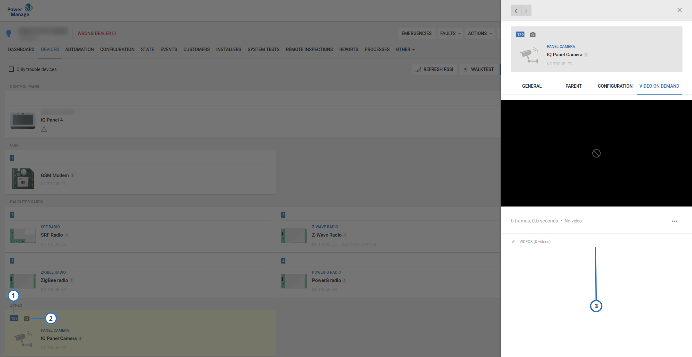
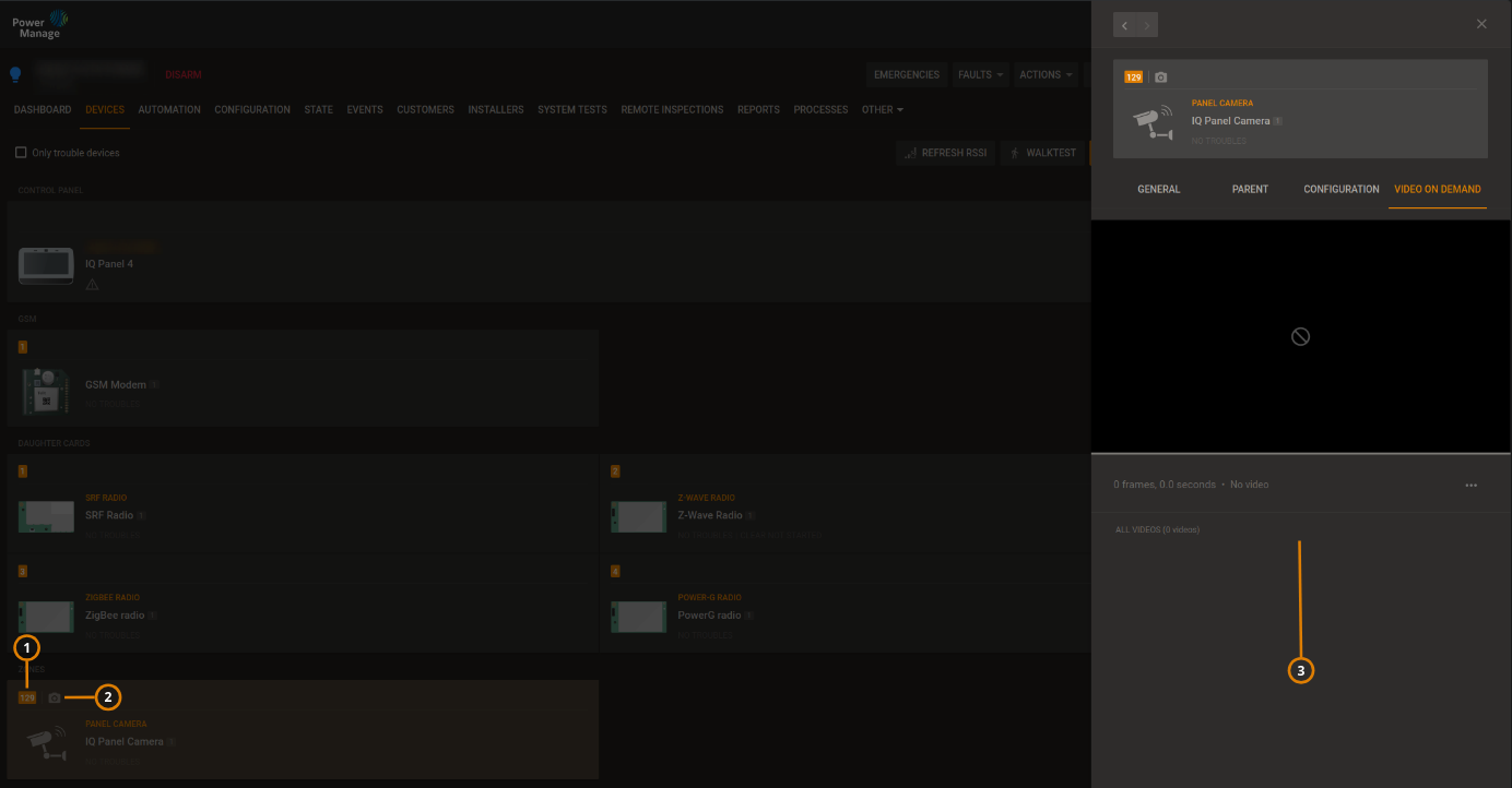
| Callout | Name | Description |
|---|---|---|
| 1 | 129 zone | Location of the IQ panel 4 internal camera information. |
| 2 | Camera icon | Click to display the camera examination pane. |
| 3 | Information pane | Use to display the camera information, to set up its options, and for video on demand request: for more information about the IQ panel 4 internal camera options, refer to the IQ panel 4 manuals. |
RTSP cameras display
The installer can use the AlarmInstall app to enroll RTSP cameras on the panel: for more information, refer to the AlarmInstall instructions.
The user can use the ConnectAlarm app to access the RTSP cameras enrolled by the installer, and view what they capture: for more information, refer to the ConenctAlarm instructions.
To display the RTPS cameras of the panel, on the navigation pane, click Equipment > the panel > DEVICES, then scroll down to the CAMERAS group:
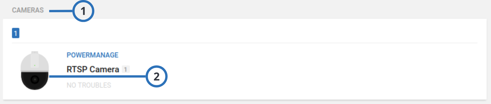
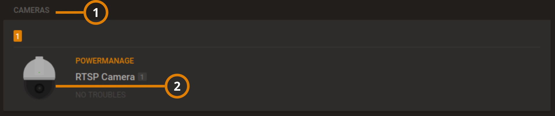
| Callout | Name | Description |
|---|---|---|
| 1 | CAMERAS | Displays the panel’s cameras. |
| 2 | RTSP Camera | Displays the RTSP camera information: click to open the examination pane. |
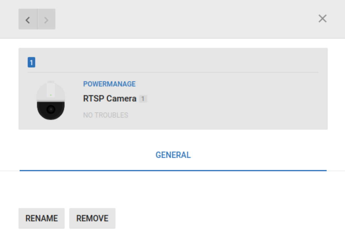
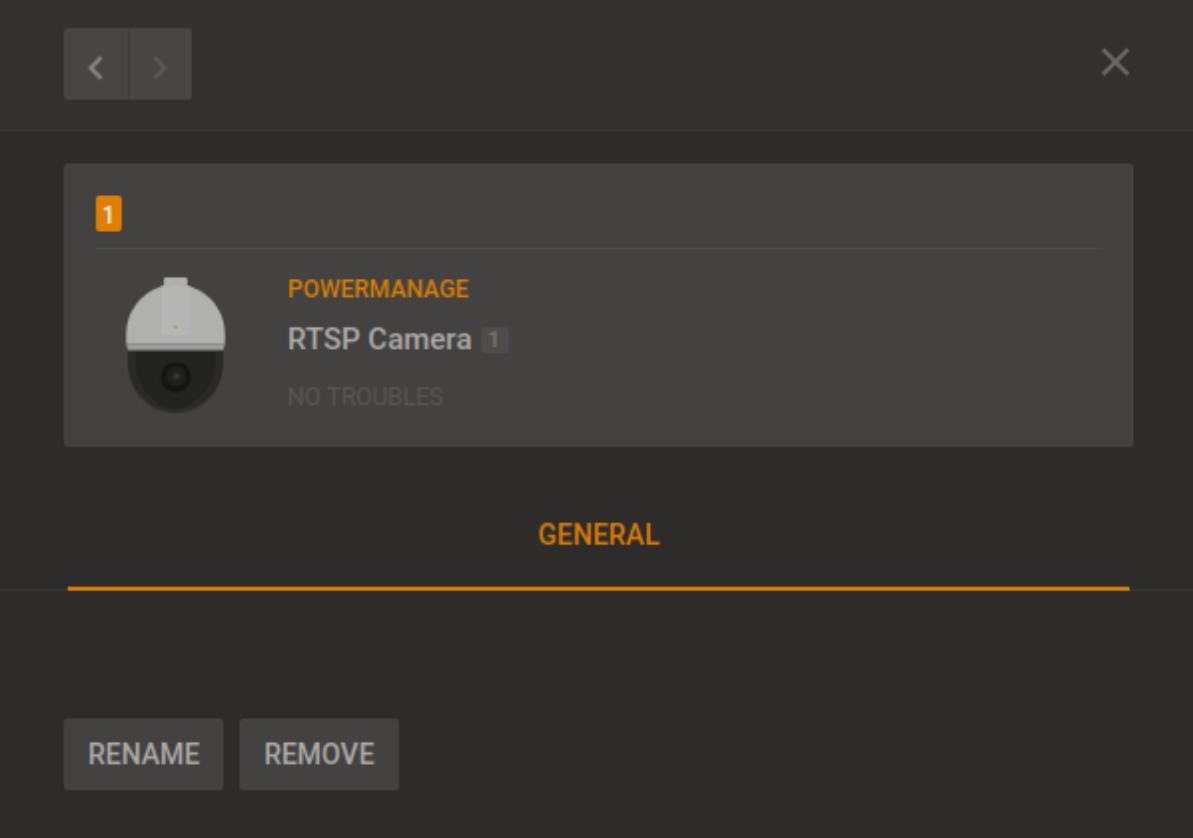
On the RTSP camera examination pane you cannot view what the camera captures
Viewing device video footage
For more information about the VIDEO ON DEMAND tab, see Using the video on demand tab.
- Click the panel name in the PANEL column on the Equipment page to open a panel in the Equipment hub.
- On the DEVICES tab, select a device that contains the video footage to view. A camera icon indicates that a device has video capabilities. For more information, see camera in Navigating the Devices tab.
- On the VIDEO ON DEMAND tab in the examination pane, click the play button in the center of the image to play the last recorded video.
To view the footage frame by frame, click the left and right arrows on the video.
Temperature and light readings on the METEO tab
View temperature and light readings from smart detectors on the METEO tab.
To find the METEO tab, in the DEVICES tab, select a smart detector and in the examination pane, click METEO. You can only open devices with the smart sensing icon in the METEO tab. For more information, see smart sensing in Navigating the Devices tab.
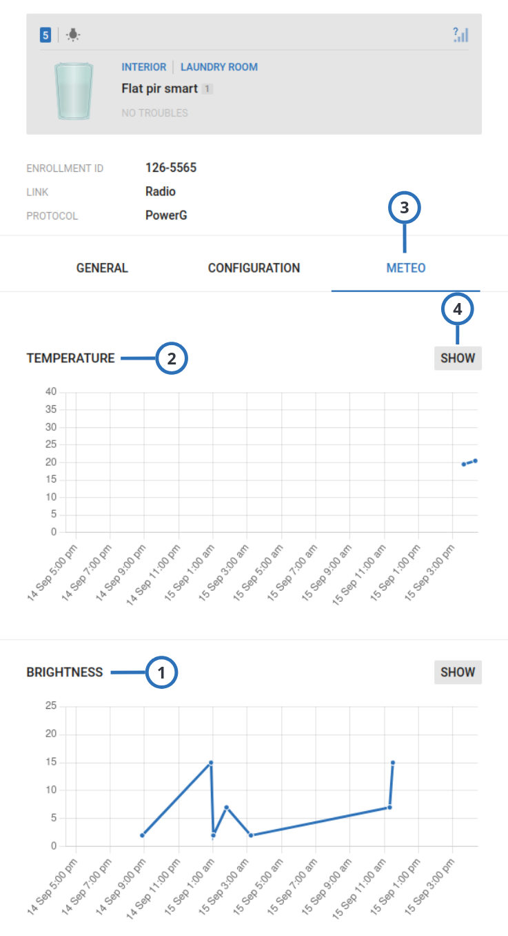
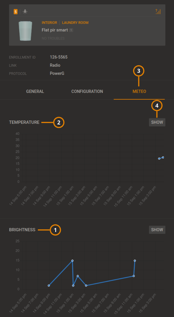
Figure. Navigating the METEO tab
| Callout | Name | Description |
|---|---|---|
| 1 | Brightness graph | View the brightness readings over a period of time. The x-axis represents the selected time period and the y-axis represents the brightness in lumens. |
| 2 | Temperature graph | View the temperature readings over a period of time. The x-axis represents the selected time period and the y-axis represents the temperature in degrees Celsius. |
| 3 | METEO tab | Click to open the METEO tab. |
| 4 | SHOW | Click to view a more detailed graph. |
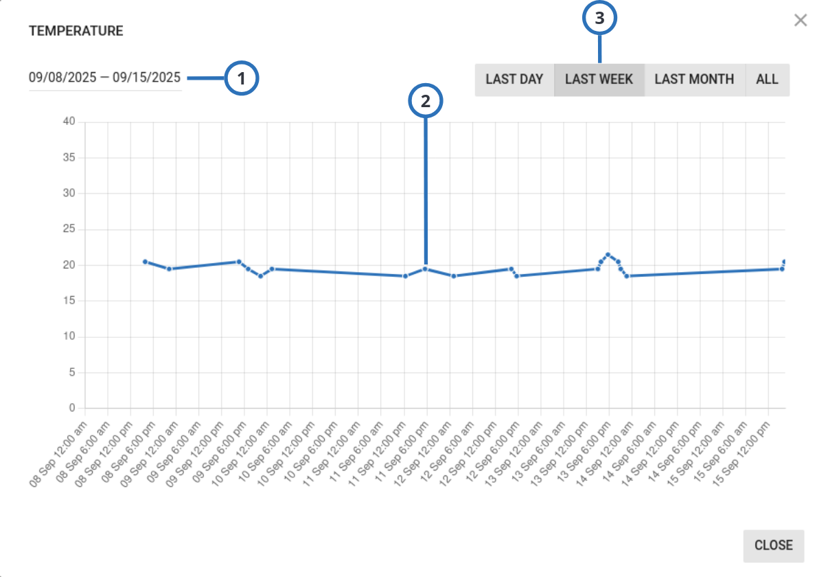
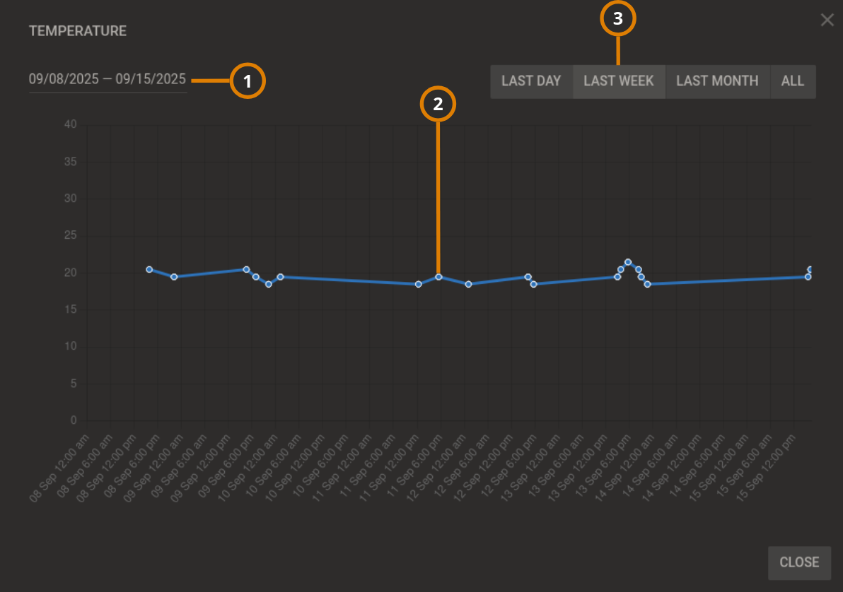
Figure. Detailed METEO graph
| Callout | Name | Description |
|---|---|---|
| 1 | Custom statistical period | Click to enter custom time period dates that change the x-axis of the graph. |
| 2 | Graph line | Each point on the graph has multiple readings. The gray lines represent the minimum and maximum readings and the blue line is the average reading. |
| 3 | Statistical period | To change the x-axis of the graph with a preset time, click LAST DAY, LAST WEEK, LAST MONTH, or ALL. |
Viewing device smart temperature or light readings
- Click the panel name in the PANEL column on the Equipment page to open a panel in the Equipment hub.
- On the devices tab, select a device that contains the smart temperature or light readings to view. A light bulb icon indicates that a device has smart temperature or light readings. For more information, see Smart sensing in Navigating the Devices tab.
- On the METEO tab in the examination pane, click SHOW to view either the Temperature or Brightness graph in detail.
If the METEO tab does not display, you must enable it. For more information, see Temperature and light readings on the METEO tab.
- Select the time period to view in the examination pane by using one of the following methods:
- To view preset time periods in the examination pane, click LAST DAY, LAST WEEK, LAST MONTH, or ALL.
- To manually enter a time period, click the date field.
The blue line indicates the average light or temperature value and the gray lines indicate the maximum and minimum values.
Using the Parent and Children tabs
If a device has other devices connected to it, the connected device appears in the examination pane on the PARENT and CHILDREN tabs on the DEVICES tab in the Equipment hub. The PARENT tab appears in the examination pane if an auxiliary device is wired to a wireless parent device. Similarly, the CHILDREN tab appears if a wireless parent device connects to one or more auxiliary wired devices.
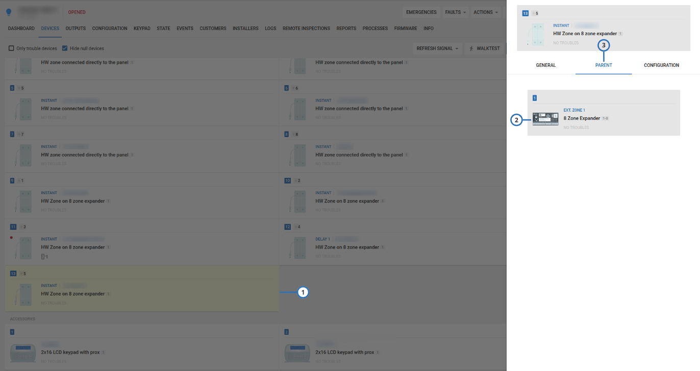
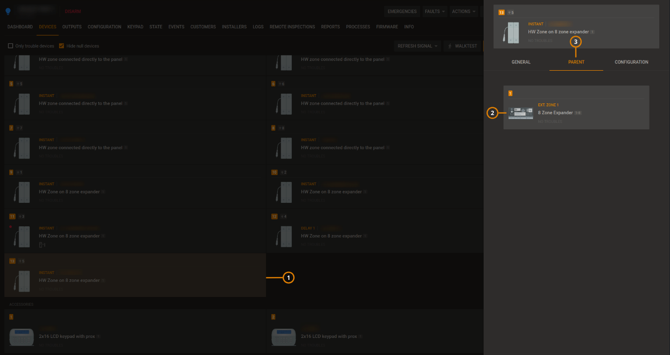
Figure. Using the PARENT tab
| Callout | Name | Description |
|---|---|---|
| 1 | Child device | The selected device is yellow. Click to open the selected device in the examination pane. note If hide null devices is checked and the device is null then it is not shown. |
| 2 | Parent device | The parent device of the selected device appears in the examination pane. |
| Click to open the parent device in the examination pane. | ||
| 3 | PARENT tab | Appears if an auxiliary device is wired to a wireless parent device. To view the parent device, in the examination pane, click the PARENT tab. |
Figure. Using the CHILDREN tab
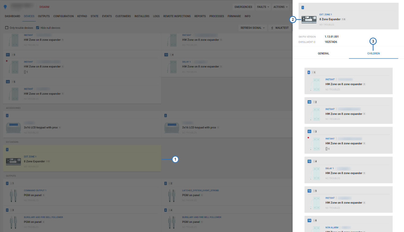
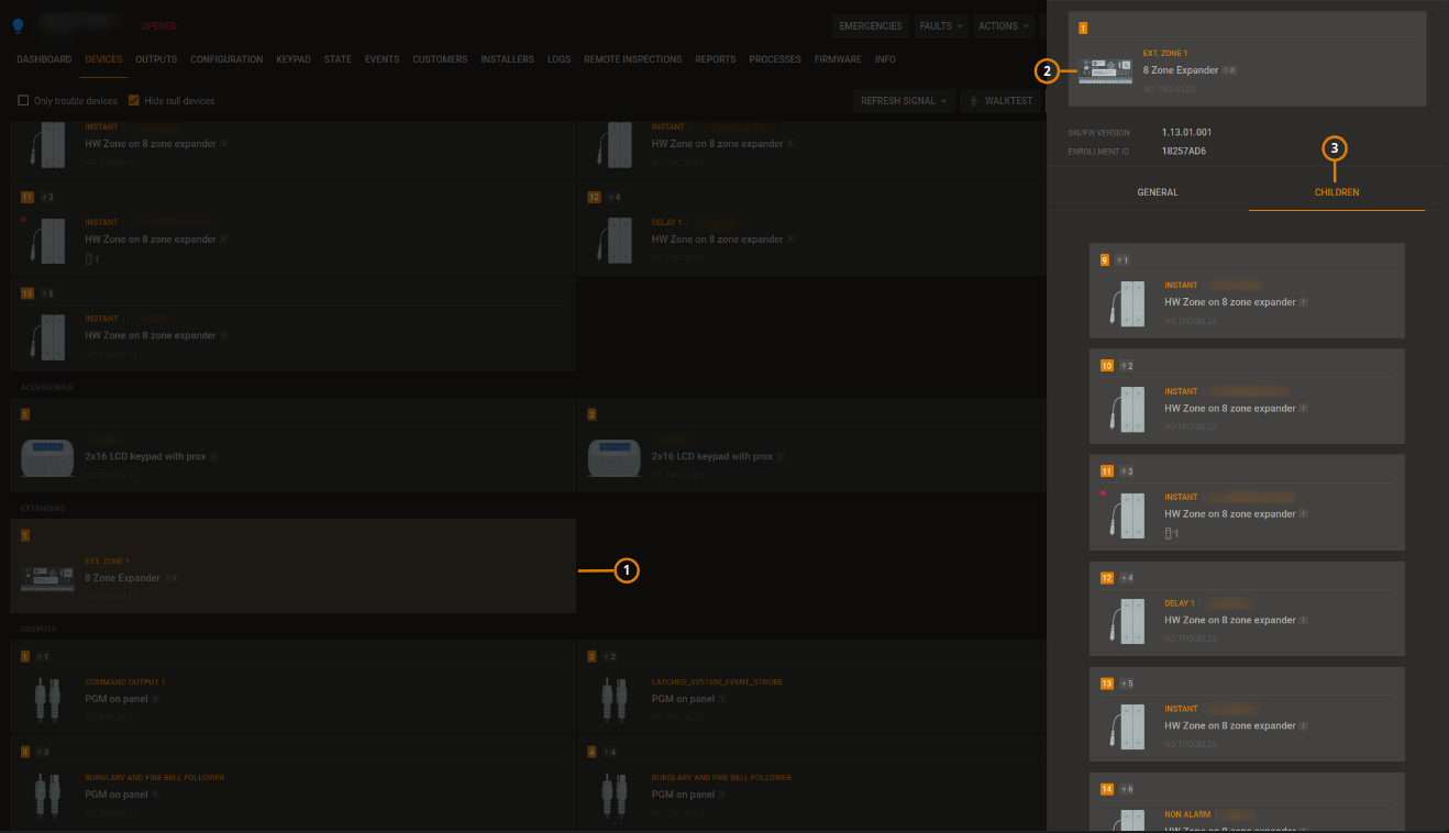
| Callout | Name | Description |
|---|---|---|
| 1 | Parent device | Click to open the required device in the examination pane. When selected, the device has a yellow background. |
| 2 | Child devices | Any child devices of the selected parent device appear in the examination pane on the CHILDREN tab. |
| Click a child device to open it in the examination pane. | ||
| 3 | CHILDREN tab | Appears if a wireless parent device connects to one or more auxiliary wired devices. To view the child device or devices, in the examination pane, click the CHILDREN tab. |